AE detection of storage tank in Zhongyuan Oilfield
Brief:Detected storage tank with acoustic emission technology.

I Acoustic emission application type
Corrosion detection of oil tank bottom
II Project overview
Entrusted by the oil and gas storage and Transportation Management Office of Zhongyuan Oilfield (Party A), Guangzhou Shenghua Technology Co., Ltd. (Party B) conducted acoustic emission inspection on the 20000m3 storage tank of Zhongyuan Oilfield in August 2006.
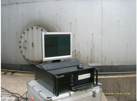
III System configuration
Acoustic emission model: for 20000 m3 storage tank, in order to ensure sufficient positioning accuracy and small signal detection rate, swaes-35 multi-channel full digital acoustic emission detection analyzer produced by Beijing Shenghua Xingye Technology Co., Ltd. is used in this test.
System performance index:
Ability to collect, analyze, process, transmit and store hits to hard disk per second (PCs. / s): 70000 / S
Ability to collect, analyze, process, transmit and store waveforms to hard disk per second (bytes MB / s): 100000 MB / S
Host noise level (DB, 0dB = 1uv; sensor output): less than 18db
IV Detection process and detection method
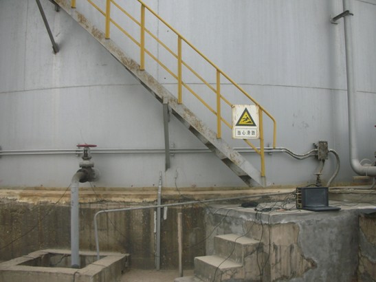
The first step is to investigate the scene and determine the sensor array
For atmospheric storage tank, just know its diameter and height, then use the tank bottom positioning in the acquisition software, input the XY axis range (greater than the tank bottom diameter), input the tank bottom diameter of 40m and the number of sensors to be arranged, and click automatic arrangement. Since the used sensors are low-frequency sensors, the spacing between sensors is less than 12m. We have arranged 16 sensors, and the spacing is less than 8m, which meets the requirements. The sensor is arranged on the tank wall 100-300mm high from the tank bottom.
The second step is to formulate the inspection scheme and determine the loading procedure
The loading test procedure of acoustic emission inspection is shown in the figure below. The pressure holding time of each stage can be determined according to the actual situation of stress release during inspection. The pressure boosting and depressurization time shall be carried out according to the requirements of GB / T 18182-2000 and in combination with the site conditions of the project.
Step 3 installation of sensor
Since the bottom plate of the tank is detected and the sound is transmitted through the medium (liquid), the sensor adopts sr50. The sensor is installed on the tank wall 100 ~ 300mm away from the tank bottom. The installation position of the sensor must be polished to remove the paint, oxide skin or oil dirt, expose the gold luster, apply the coupling agent and fix the sensor. The sensor is a vulnerable device, which should be handled with care to prevent collision.
Step 4 instrument debugging
Set the working parameters of the instrument hardware, which generally include threshold (35dB), parameter interval (1000 µ s), locking time (2000 µ s), sampling frequency (625kHz), sound velocity (1.2km / s), etc.
For background noise measurement, the threshold is generally 5 ~ 10dB higher than the background noise. Most of the detection is carried out under the medium sensitivity with the threshold of 35 ~ 55dB, and the most commonly used threshold is 40dB. The instrument must be well grounded before collection. If the background noise is large, check whether there is a noise source on site, whether the medium inside the tank flows, whether the sensor is well coupled, etc.
Channel sensitivity calibration
If a channel cannot receive a signal during calibration, check whether the acquisition card of the channel is turned on, and then check the function selection of the channel in the channel parameters. If 3 is selected, no signal can be received; If there are no problems, check the connection of the front end and whether the front amplifier is connected reversely.
Attenuation measurement
Source location calibration
The fifth step is to load the experimental program and data acquisition
The acoustic emission data of each stage are shown as follows:
Before collection, you must remember to save the data first, that is, select the save data check box, and then start collection. After collection, the data will be automatically saved to the location you selected. In the process of data collection, it is necessary to observe the changes of data at all times. It is best for on-site personnel to stay away from the container to avoid unnecessary interference. In case of man-made collision with the tank body, the time and location of the collision shall be recorded for subsequent analysis; If the number of impacts increases rapidly with time, the loading shall be stopped until the cause is found