Your position:HOME > PRODUCTS > Benchtop AE System > SAEU3H Multi-channel AE System >
Multi-Channel AE Chassis
Model:
SAEU3H chassis
Description:
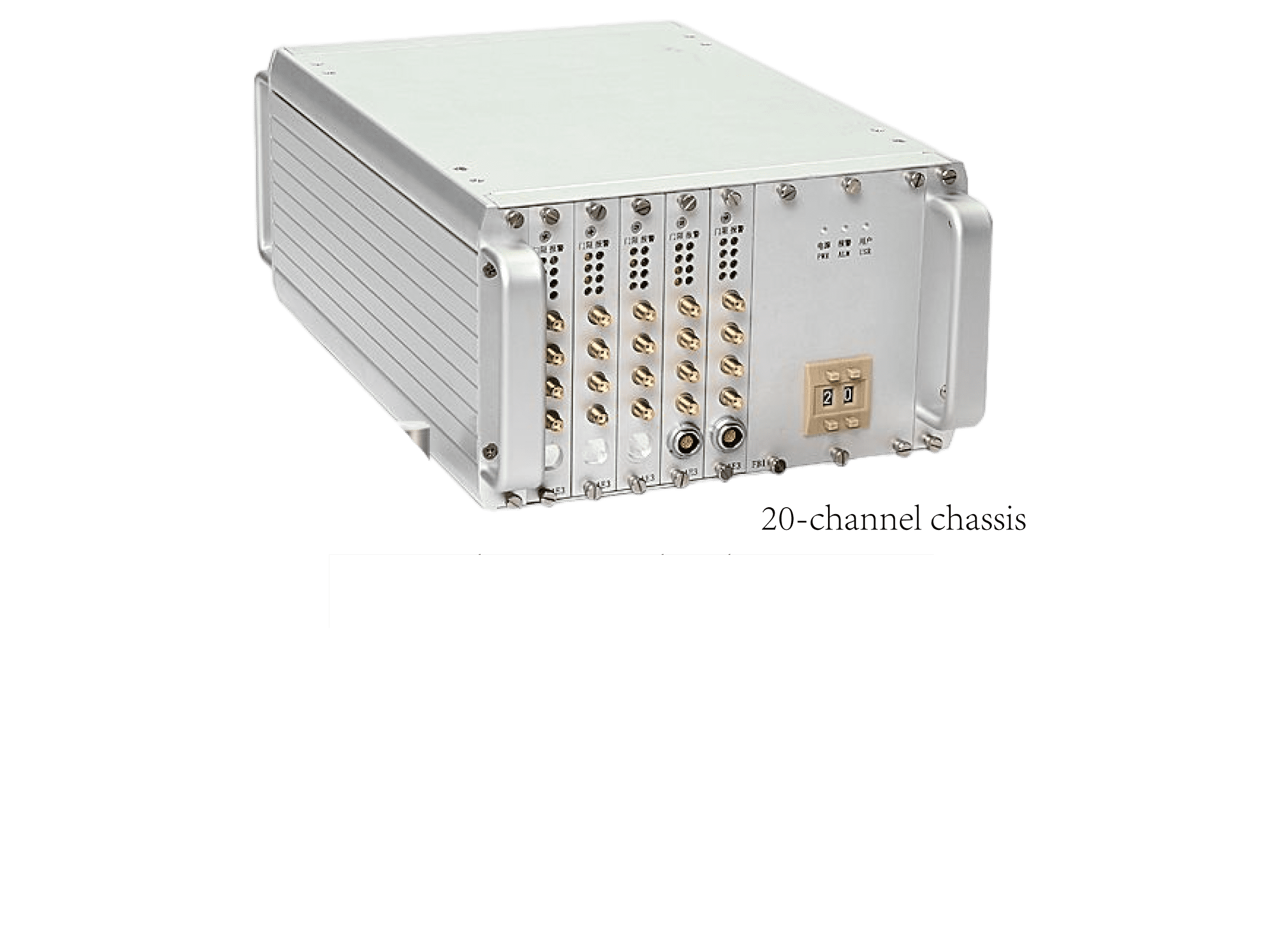
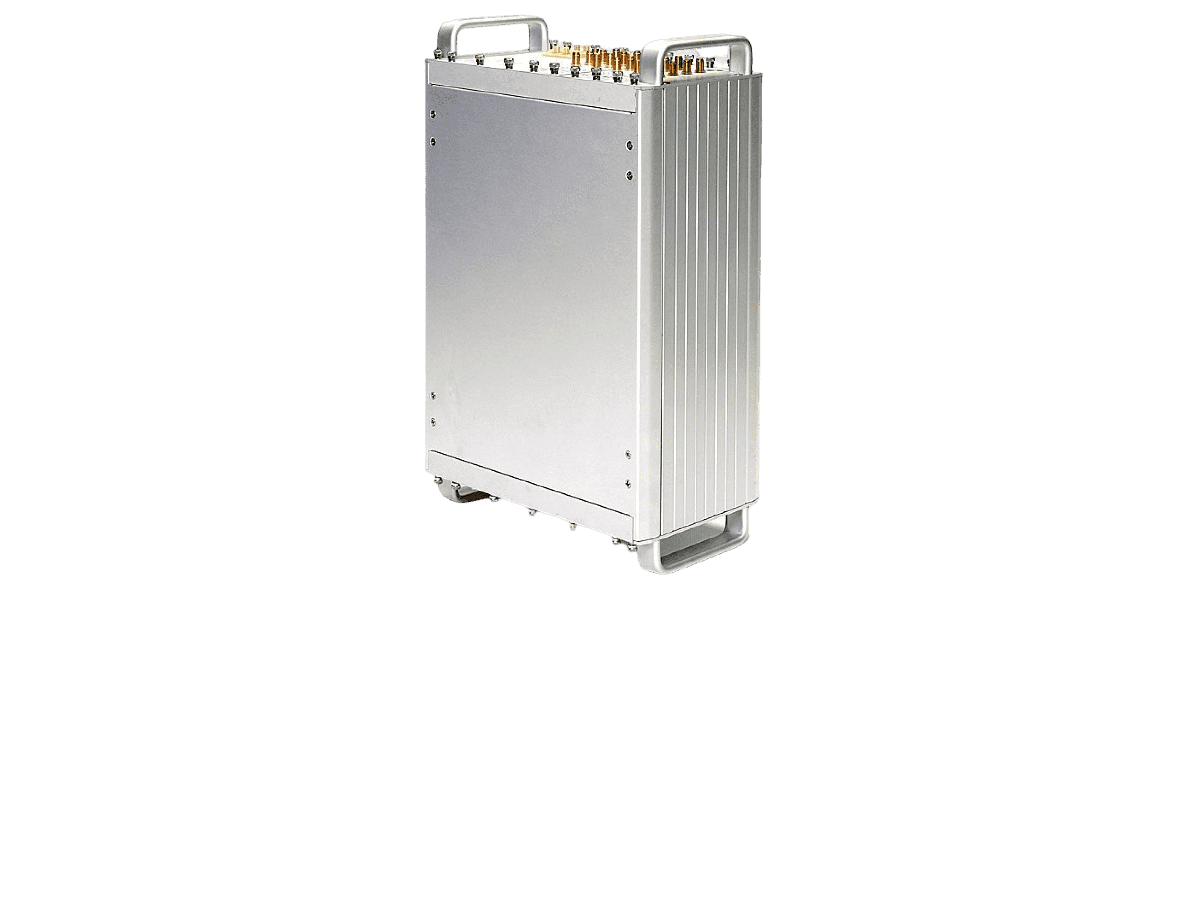
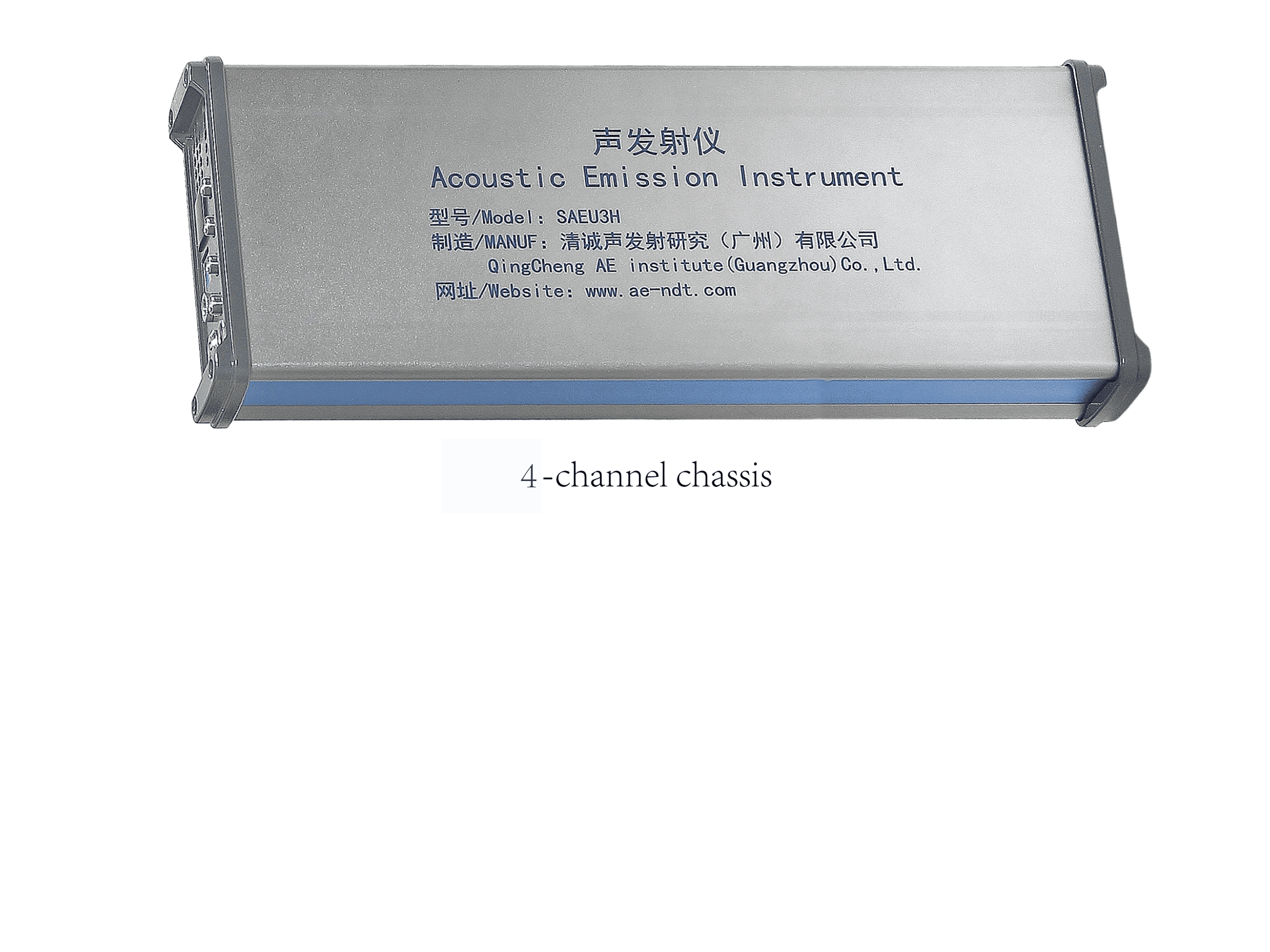
We have three types of AE chassis, 4-channel, 20-channel and 48-channel, and the chassis can be cascaded into larger systems with more than 100 channels which could meet most requirements of industrial applications and laboratory research.
Features:
Good compatibility, can be cascaded into a large detection system. Compact design and good portability. USB3.0 interface with high transmission rate
ENQUIRY NOWCONTACT:+86-20-32290092
SAEU3H Chassis Series
We have three types of AE chassis, 4-channel, 20-channel and 48-channel, and the chassis can be cascaded into larger systems with more than 100 channels which could meet most requirements of industrial applications and laboratory research.
Technical Specifications
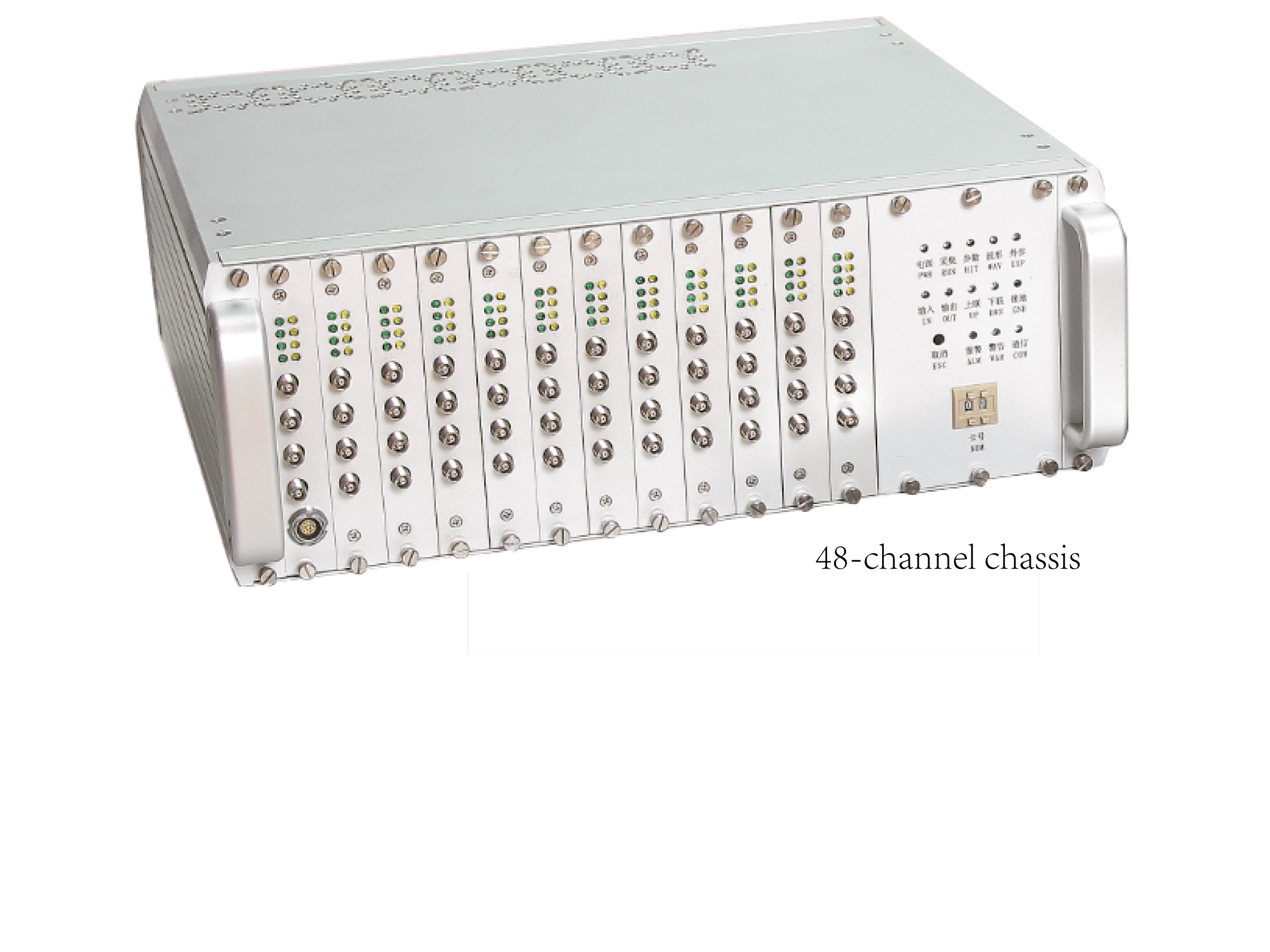
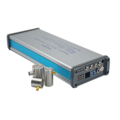
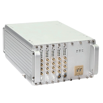
| Chassis Type | 4-Channel Chassis | 20-Channel Chassis | 48-Channel Chassis |
|---|---|---|---|
| Photo |
 |
 |
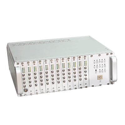 |
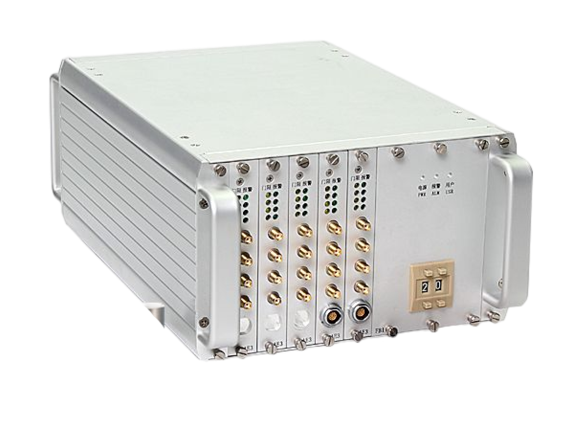
| Max. channels | 1 slot 4 channels | 5 slots 20 channels | 12 slots 48 channels |
| Size (W x L x H mm) | 125 x 310 x 50 | 225 x 363 x 150 | 368 x 363 x 150 |
| Weight (g) | 1300 | 3700 | 5160 |
| Power consumption(W) | 2.4 | 9.5 | 22 |
| Shell material | Aluminum alloy | Aluminum alloy | Aluminum alloy |
| Working temp. (℃) | -10 to 45 | -10 to 45 | -10 to 45 |
- High integration and easy to carry
- The chassis is made of all-aluminum alloy material, and the entire chassis frame and panel are conductively interconnected and fully shielded to enhance the ability to resist electromagnetic interference.
- The power supply and heat dissipation are precisely designed according to thermodynamics and aerodynamics to ensure uniform heat dissipation, reliable and stable long-term operation under the most demanding conditions.
- High-end standard industrial chassis similar to PXI plug-in function module structure, with good expansibility. Function module cards such as acquisition boards are relatively independent from the chassis, making it easy to maintain and upgrade the equipment;
- The panel has multiple sets of indicator lights to display power, USB communication, operation, parameters, waveform, alarms, external parameters, etc., making it easy to observe the operating status of the equipment. External trigger, alarm output;
- The SAEU3H acquisition system comes standard with USB3.0 data communication, which can meet the communication and storage of instantaneous large amounts of data.
- A single USB3.0 interface connected to a computer has a real-time continuous throughput rate of up to 300MB/sec, which can meet the collection of 3 million sets of characteristic parameters/second or the continuous waveform collection of 300MB/sec.
- The innovative motherboard bus design enables intelligent management of data collected from each acquisition, and can be expanded to other types of boards to achieve long-term monitoring, storage, and long-distance transmission functions.
- The chassis model, the number of chassis, and the number of AE boards can be configured according to the needs to form a multi-channel model system. Multiple chassis can be cascaded to form a large channel number acoustic emission system. Each chassis can be used as a host alone and can be expanded to more than 100 channels.

Cascade schematic diagram
SAEU3H Chassis Panel Introduction
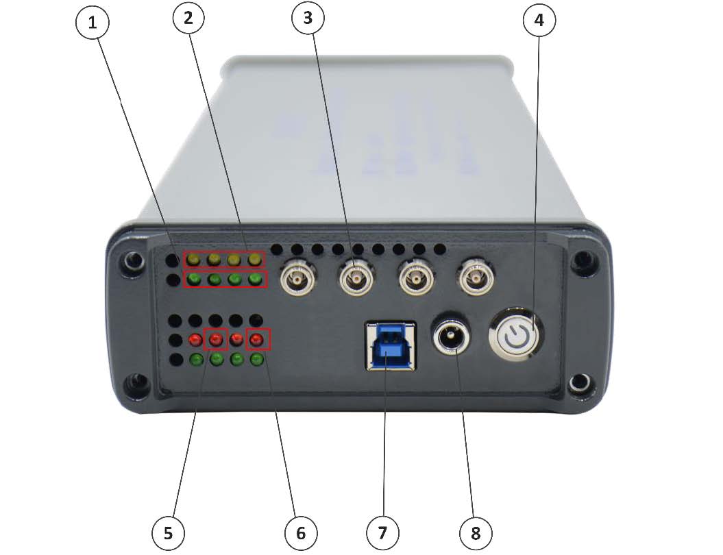
①Signal Indicators (Green LEDs): when there is a signal in the channel exceeding the set threshold, the LED will blink once. Each LED represents one channel and the LED order from left to right are channel #1, 2, 3, 4.
②Preamplifier Indicators (Yellow LEDs): when finishing the hardware configuration setup in the SWAE software, the system will check if there are preamplifiers (either internal inside the sensors or external) connected to the channels. If it detects that the preamp is connected, the corresponding yellow LED light turns on and the system starts to supply phantom power to the preamp. Each LED represents one channel and the LED order from left to right are channel #1, 2, 3, 4. It doesn’t affect the normal operations.
③Channel Connector: C5 (LEMO-00) type connector to connect with the preamplifier and sensor. Each connector represents one channel and the channel order from left to right is channel #1, 2, 3, 4.
④Power Switch: hardware power switch of the instrument.
⑤Status Indicator: the second red LED from the left is the indicator showing the sampling status of the instrument. The LED light on means the instrument is now in sampling mode and actively collecting data.
⑥Power Indicator: the first red LED from the right is the power status light. When the hardware power is tuned on, the power indicator light is on.
⑦USB Connector: uses USB3.0 type B connector for data and control communication between the instrument and the PC.
⑧Power Connector: the power connector of the instrument. It requires 12V DC.
Note: The structure of 20-channel chassis is almost the same as that of 48-channel chassis.
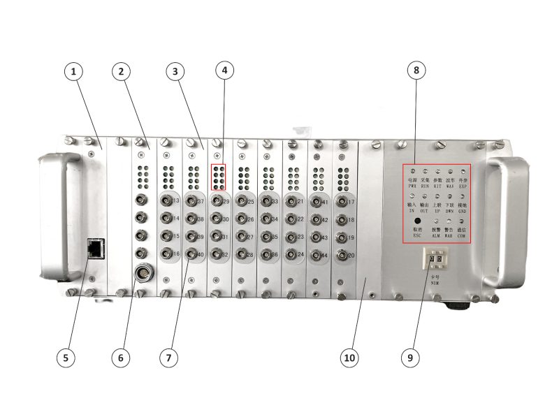
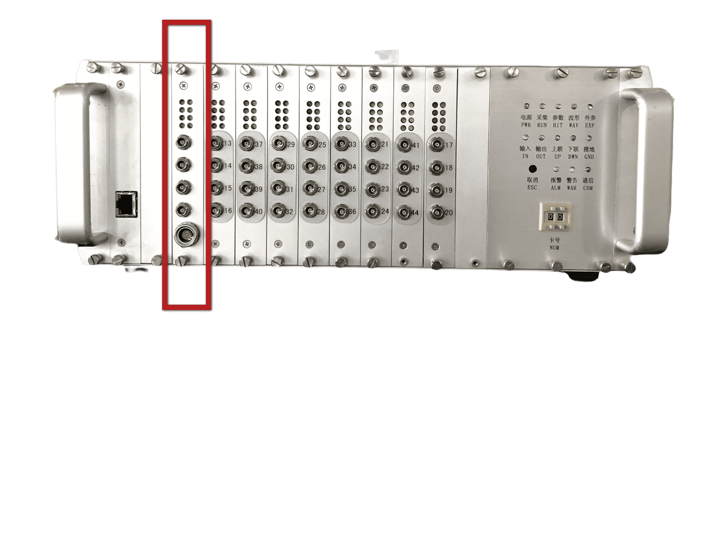
①Network Communication Board: optional and detachable. Substitute data communication port (Ethernet port) in addition to USB3.0 port.
②EX-parameter 4-channel AE Board: optional and detachable. The AE board with one standard AE board plus a 16-pin LEMO port for external parameter box connection. Each board has 4 channels.
③Standard 4-channel AE board: detachable. Standard AE board for AE data acquisition and processing. Each board has 4 channels.
④Channel Indicators: Each row of two LEDs (green on the left, yellow on the right) represents one channel and the channel order is ascending from top to bottom and from left to right. The channel number is labeled next to the C5 (LEMO-00) type connector.
a. Signal Indicators (Green LEDs): when there is a signal in the channel exceeding the set threshold, the LED will blink once.
b. Preamplifier Indicators (Yellow LEDs): when finishing the hardware configuration setup in the SWAE software, the system will check if there are preamplifiers (either internal inside the sensors or external) connected to the channels. If it detects that the preamp is connected, the corresponding yellow LED light turns on and the system starts to supply phantom power to the preamp. It doesn’t affect the normal operations.
⑤Ethernet Connector of the Network Communication Board: female RJ45 port.
⑥EX-Parameter Box Connector: 16-pin LEMO port.
⑦Channel Connector: C5 (LEMO-00) type connector to connect with the preamplifier and sensor.
⑧Status Indicators: each LED has both Chinese and English labels below indicating its function.
⑨Number (NUM): indicates the number of AE boards ahead of this chassis when the chassis is cascaded to a larger system. If it is the only chassis, make sure it is “00”.
⑩Cover Panel: detachable. The cover panel is to cover the empty board slots to protect the chassis from having openings.
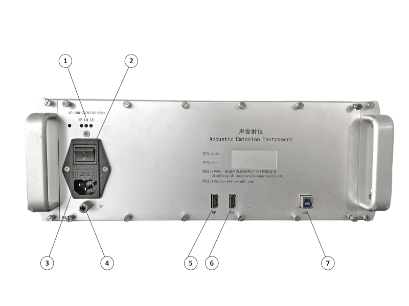
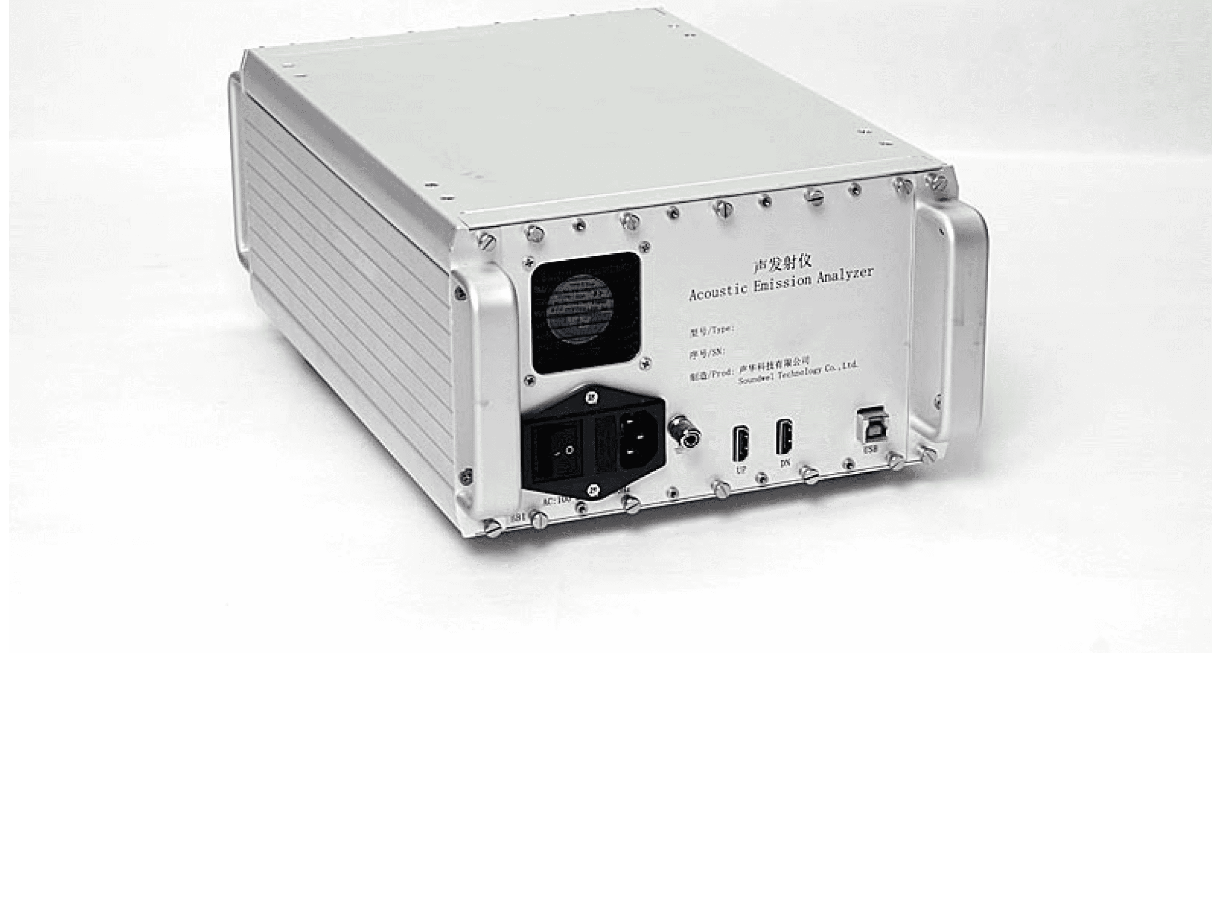
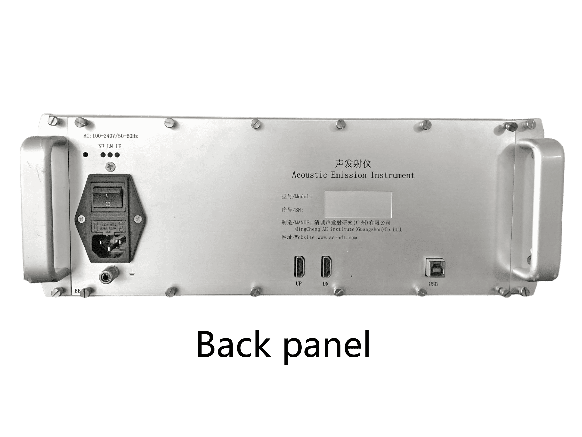
①Power Indicator: these three LEDs are the power status lights. When the hardware power is turned on, the power indicator lights are on.
②Power Switch: hardware power switch of the instrument.
③Power Connector: the power connector of the instrument. It can support AC 100-240V 50-60Hz input.
④Ground Connector
⑤UP: HDMI connector for connecting to the upper level chassis prior to this chassis when cascading. After connection, remember to increase the NUM in the front panel of the chassis according to actual situation.
⑥DN: HDMI connector for connecting to the lower level chassis after this chassis when cascading.
⑦USB Connector: uses USB3.0 type B connector for data and control communication between the instrument and the PC.
Further Information
 SAEU3H Chassis Panel Introduction Sheet.pdf