Your position:HOME > PRODUCTS > Preamplifier >
PAS(SAEPA2) Acoustic Emission Multi-functional Preamplifier
Model:
PAS(SAEPA2)
Description:
Available in both phantom and adapter power supply, and it is compatible with most common sensors and acoustic emission acquisition boards on the market.
Features:
4 filters and 3 gains, and can be connected to differential sensors. It is available in both phantom and adapter power supply
ENQUIRY NOWCONTACT:+86-20-32290092
PAS(SAEPA2) Acoustic Emission Multi-functional Preamplifier
Description
The PAS preamplifier is an analog signal amplification circuit, whose input is the voltage output by the acoustic emission sensor, and the output is the amplified analog signal. The voltage signal output by the acoustic emission sensor is sometimes as low as a few microvolts. If such a weak signal is transmitted over a long distance, the intensity will inevitably decrease. The original sensor signal needs to be amplified by several times before long transmission. The commonly used amplification factor is by 40dB, and then transmitted to the signal acquisition unit through a high-frequency coaxial cable.
The acoustic emission preamplifier should have impedance matching and transformation functions. In order to prevent the impact of excessive input signals, it should also have protection capabilities against electrical shocks and recovery capabilities against blocking phenomena. And it has a relatively large output dynamic range.
Main Features
- The PAS preamplifier is a broadband universal type that can be used for most common models of sensors and acoustic emission acquisition cards from various manufacturers;
- The preamplifier gain has three options: 20/40/60dB;
- Single ended/differential signal input methods;
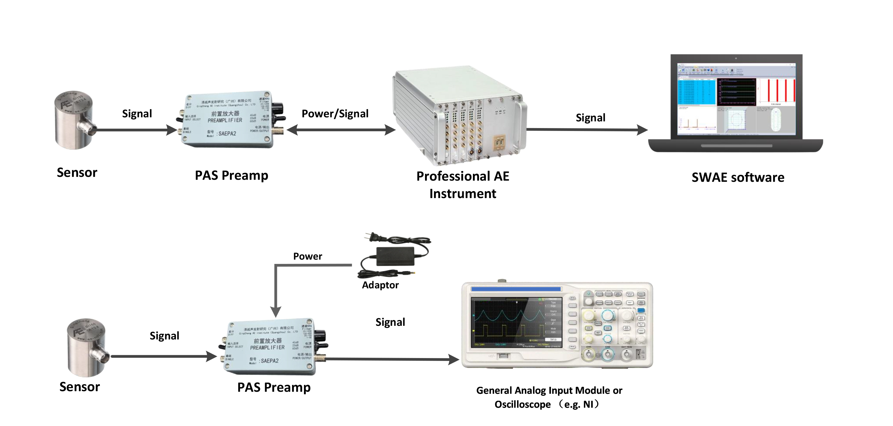
- There are two powering options available: phantom power supply, which is carried and supplied by the data acquisition unit followed by; or directly powered by an external power adaptor;
- Built-in analog filters and there are four ranges of frequency filters for selection;
- Automatic Sensor Testing (AST) function, which can send a test signal to the sensor (under phantom power supply);
- Metal shell, shielded from electromagnetic interference, and resistant to electrical shocking.
Technical Specifications
| Gain | 20/40/60dB |
| Response frequency | 1.3kHz~1.2MHz |
| Noise | <24dB |
| Filter |
20kHz-1200kHz 100kHz-400kHz 20kHz-120kHz 1kHz-40kHz |
| Output range | ±10V(Vpp) |
| Input capacitive reactance | 15pF |
| Working voltage | 24V-32V |
| Impendence | 50Ω |
| Quiescent current | 31 mA |
| Maximum current | 100 mA |
| Working temp. | -20℃~+60℃ |
| Dimensions (LxWxT) | 110mm×65mm×37mm |
| Weight | 300 g |
| Protection level | IP65 |
| Shell material | Cast aluminium |
| Connector | BNC |
Notes
1. The output impedance of the preamplifier must match with the input impedance of the downstream instruments (such as professional AE acquisition unit, DAQ, or oscilloscope). Otherwise it will lead to the gain of the preamplifier to deviate from the nominal gain value, resulting in signal amplitude deviation.
2. If the output of the PAS preamplifier connects to the non professional AE acquisition units (e.g. DAQ or oscilloscope), an external power adaptor is required. On the other hand, a PPS is required to supply power to the preamplifier for the PAV preamp or built-in preamp.
3. Connection must be correct. The following three wrong operations may lead to damages to the preamplifier:
a. The input voltage is 25% higher than the power supply requirement.
b. The input and the output of the PAS preamp are reversed connected.
c. The positive and negative polarities of the power supply are reversed, when the external DC 28V is applied.
PAS preamplifier connection diagram

Further Information


