
Pressure Vessel Acoustic Emission Testing and Monitoring
A complete AE testing solution for detecting active cracks, leakage, weld activity and structural damage in pressure vessels during pressure testing or in-service monitoring
QAWRUMS provides complete acoustic emission testing systems for pressure vessel inspection, including AE sensors, preamplifiers, signal cables, multi-channel acquisition systems, pressure input, software, source location analysis and reporting support.
- Introduction
- Testing Workflow
- System Configuration
- Data Analysis
- Cases & Materials
Acoustic Emission Testing for Pressure Vessels
Acoustic emission testing is a non-destructive testing method used to detect active damage sources in pressure vessels and pressure-retaining equipment. Unlike conventional local inspection methods, AE testing can monitor the whole structure during one loading or pressure test process.
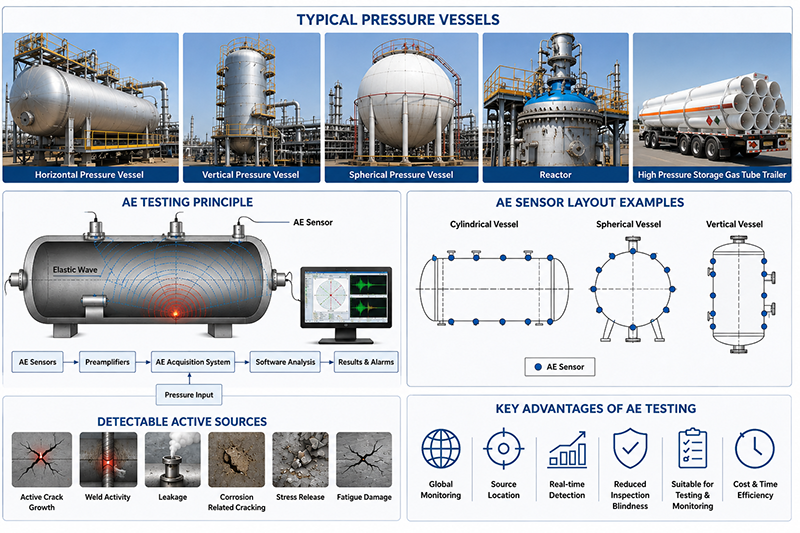
When a pressure vessel is pressurized, active defects may generate acoustic emission signals. These signals can be detected by sensors installed on the vessel surface. By analyzing signal parameters and arrival time differences between sensors, the system can help locate active source areas and evaluate their activity.
This makes AE testing especially suitable for pressure vessels where the defect location is unknown, access is limited, shutdown time is expensive, or real-time monitoring during pressure loading is required.
Typical Applications
QAWRUMS pressure vessel acoustic emission testing systems can be used for:
- Pressure vessels
- Boilers and steam drums
- Reactors and separators
- Absorption towers and columns
- Heat exchangers
- Gas cylinders
- High pressure storage tube trailer
- Other pressure-retaining equipment
What Can Be Detected?
AE testing is mainly sensitive to active defects and active acoustic sources, including:
- Active crack growth
- Weld activity
- Leakage
- Fatigue damage
- Stress corrosion cracking
- Abnormal friction or stress release
- Corrosion-related cracking or leakage
A completely inactive defect may not generate acoustic emission signals. Therefore,AE testing is most effective when the pressure vessel is under pressure, load, thermal stress or operating conditions.
Key Advantages
-
Global Monitoring
Multiple AE sensors can monitor a large pressure vessel as a whole, helping identify active source areas without inspecting every local point manually. -
Real-Time Detection During Loading
AE testing can be performed during hydrostatic testing, pneumatic testing, proof testing or controlled pressure loading. Active defects are more likely to generate detectable signals under stress. -
Source Location Capability
With multiple sensors, the system can estimate the location of acoustic emission sources and help guide follow-up inspection. -
Reduced Inspection Blindness
AE testing helps operators focus UT, PAUT, MT, PT or other NDT methods on suspicious areas instead of inspecting the entire vessel blindly. -
Suitable for Testing and Monitoring
The same AE technology can be used for short-term pressure test monitoring, temporary diagnosis or long-term online monitoring of critical equipment.
How the Pressure Vessel AE Test Is Performed
A pressure vessel AE test is usually performed as a systematic engineering process. The typical workflow includes equipment information review, site survey, test plan preparation, sensor installation, system debugging, pressure loading, signal acquisition, data analysis, source evaluation and final reporting.
Step 1: Equipment Data Review
Before testing, the vessel information should be reviewed to understand the inspection object and prepare the AE test plan.
Typical information includes:
- Equipment drawings
- Vessel geometry and dimensions
- Material and wall thickness
- Design pressure and operating pressure
- Operating temperature
- Working medium
- Manufacturing records
- Previous inspection records
- Repair or modification history
- Known defect information
- Loading and operation history
This step helps determine the inspection purpose, sensor layout, channel number, pressure procedure and expected risk areas.
Step 2: Site Survey and Noise Evaluation
Before installing the system, the site conditions should be checked. Possible noise sources should be identified and reduced as much as possible.
Common noise sources include:
- Mechanical vibration
- Fluid flow noise
- Scaffolding friction
- Movement of internal or external accessories
- Electromagnetic interference
- Wind, rain or other environmental interference
- Loose fixtures or structural components
Background noise evaluation is important because AE testing relies on detecting weak acoustic signals from active defects. If noise is too strong, it may affect the reliability of the test.
Step 3: Test Plan and Sensor Layout
The test plan should define the number of channels, sensor positions, sensor spacing, source location method, loading procedure, acquisition parameters and evaluation method.
For large or complex pressure vessels, sensor layout should be designed according to:
- Vessel geometry
- Material
- Wall thickness
- Acoustic attenuation
- Expected source areas
- Weld distribution
- Nozzle and opening positions
- High-stress areas
- Required location accuracy
For cylindrical pressure vessels, sensors are commonly arranged around the shell, weld seams, heads and nozzle areas. For spherical or irregular vessels, triangular or customized sensor arrays may be used.
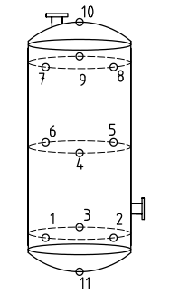 Figure A.1 - Cylindrical vessel |
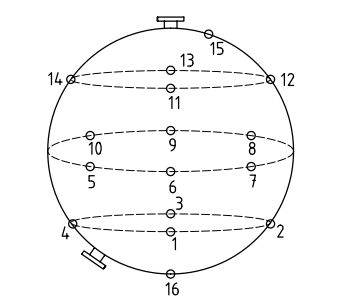 Figure A.2 - Spherical vessel |
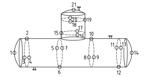 Figure A.3 - Assembled steel vessel |
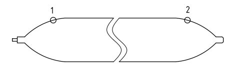 Figure A.4 - Gas cylinder |
Note: each number point means the AE sensor location.
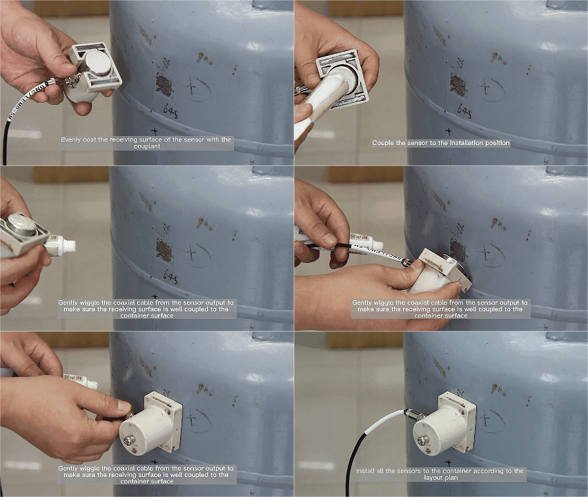
Step 4: Sensor Installation and Coupling
AE sensors are installed on prepared surface areas of the vessel. Good acoustic coupling is essential for reliable signal transmission.
Typical checks include:
1) Mark the sensor positions according to the layout plan.
2) Prepare the surface (remove coating or insulation and polish) to ensure good acoustic contact.
3) Apply suitable couplant.
4) Fix the sensors with magnetic holders, clamps or other fixtures.
5) Connect sensors to preamplifiers and the acquisition system.
6) Check insulation, cable connection and channel status.
For high-temperature or low-temperature vessels, special sensors, thermal protection or waveguide rods may be used.
Step 5: System Debugging and Calibration
Before formal testing, the AE system should be checked and calibrated. This helps confirm that sensors, preamplifiers, cables and acquisition channels are working properly.
Typical checks include:
- Channel sensitivity verification
- Background noise measurement
- Threshold setting
- Gain setting
- Pencil lead break test or simulated source test
- Attenuation measurement
- Sound velocity measurement
- Source location calibration
- Pressure signal input verification
Step 6: AE Monitoring During Pressure Loading
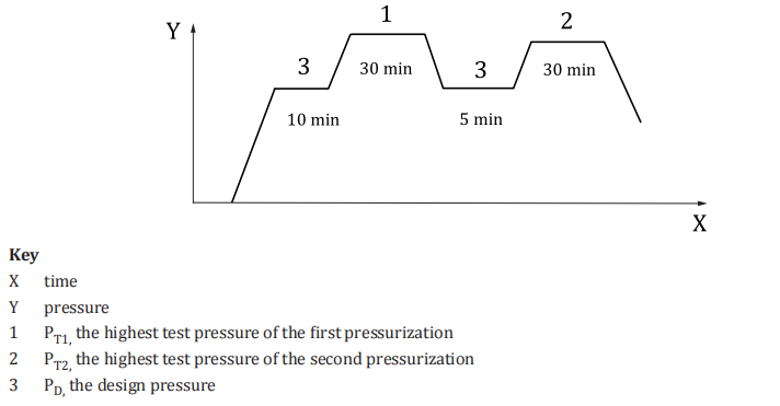
During hydrostatic or pneumatic testing, AE signal acquisition is performed while the pressure is increased and held according to the test procedure.
The system records AE activity during:
- Pressure increase
- Pressure holding
- Pressure reduction
- Re-pressurization, if required
Signals that increase rapidly, repeatedly appear from the same source area, or continue during pressure holding may require attention.
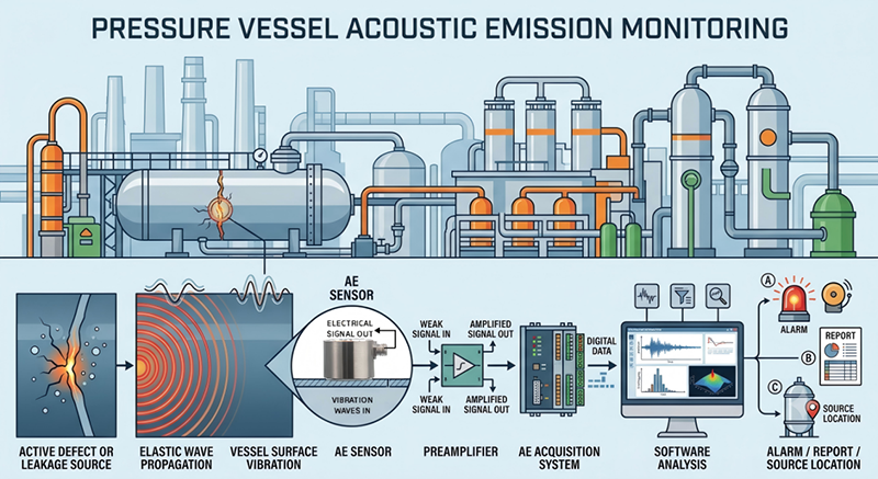
Complete AE Testing System for Pressure Vessels
QAWRUMS provides a complete acoustic emission testing system for pressure vessel inspection. The system can be configured according to vessel size, number of channels, testing purpose, temperature, site environment and monitoring duration.
Main System Components
1) AE Sensors
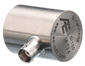
AE sensors convert the micro mechanical vibration on the vessel surface into electrical signals. For metal pressure vessels, sensors in the 100 kHz to 400 kHz range are commonly used depending on material, attenuation, noise and inspection purpose.
 |
|
Sensor selection may include:
- Resonant AE sensors for high-sensitivity detection
- Broadband AE sensors for waveform and frequency analysis
- High-temperature AE sensors for hot surfaces
- Differential sensors for noisy environments
- Waveguide installation for very high-temperature applications
2) Preamplifiers
The AE signal generated by the sensor is usually weak. A preamplifier is used to amplify the signal before it is transmitted to the acquisition system. Common gain options include 34 dB, 40 dB or other gain settings depending on the application. Or integral sensor with preamplifier built-in can be used as compact design.
3) Signal Cables
Low-noise coaxial cables are used to transmit the AE signal from the sensor or preamplifier to the acquisition system. Cable length, shielding and site routing should be considered during system design.
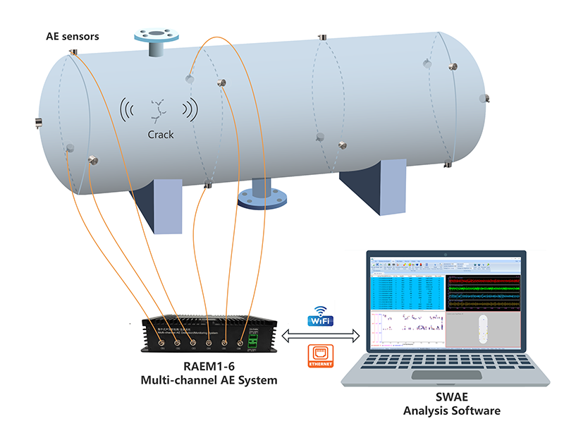
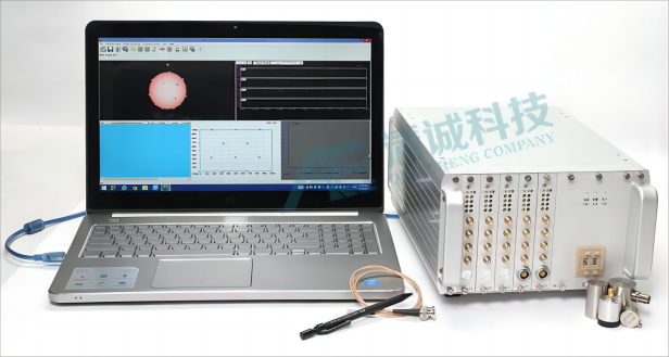
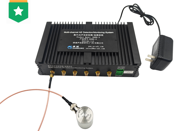
4) AE Acquisition System
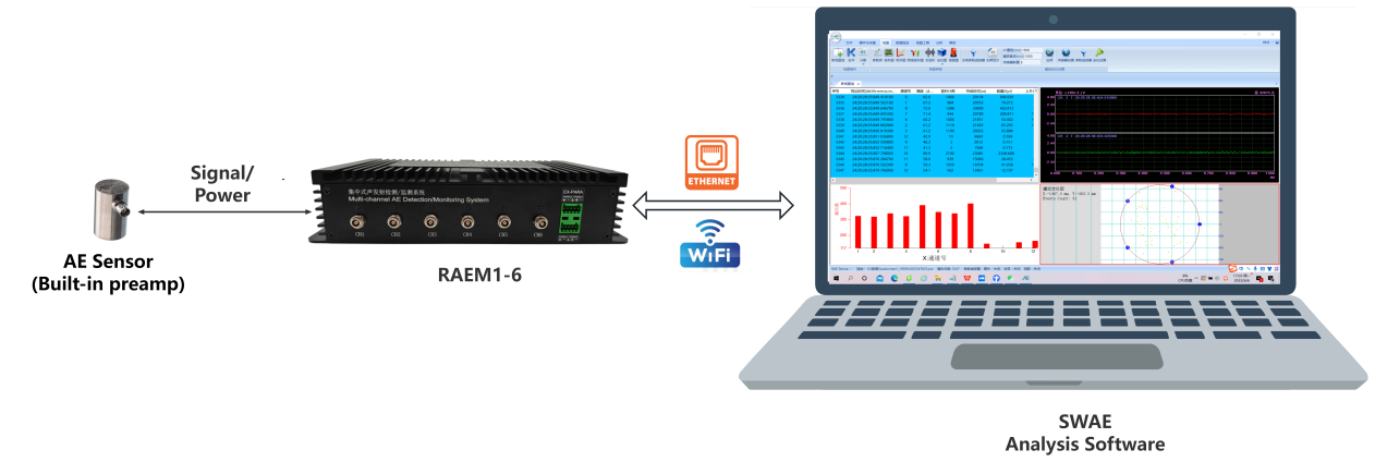
The acquisition system collects AE signals from multiple channels and processes them in real time. A pressure vessel AE system should support multi-channel acquisition, source location and parameter analysis.
Typical functions include:
- Multi-channel AE signal acquisition
- Extracted AE feature parameters (Amplitude/energy/duration etc.) measurement
- Hit and event counting
- ASL or RMS analysis
- Pressure input recording
- Planar or cylindrical source location
- Real-time graphs and alarm display
- Waveform recording and analysis
 |
|
 |
|
5) Pressure Input*
For pressure test monitoring, pressure data might be recorded together with AE signals through the external parameter (input) channels. This allows the operator to evaluate AE activity together with the pressure curve.
6) Software
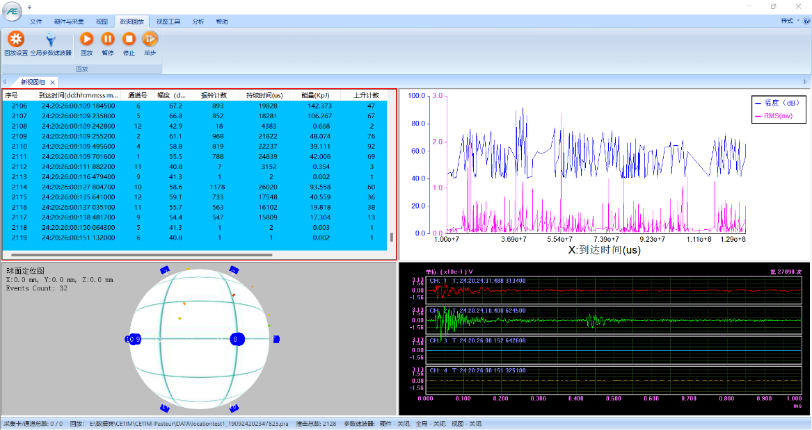
AE software provides real-time display, data recording, parameter filtering, waveform analysis, source location, trend analysis and reporting.
Typical software views include:
- Source location map
- AE event list
- Amplitude history
- Energy history
- Hit rate trend
- Pressure history as external input
- Cumulative count curve
- Waveform display
- Alarm status
7) Accessories
The system may also include:
- Magnetic holders
- Couplant
- Sensor mounting fixtures
- Calibration tools
- Pencil lead break tools
- Power supply
- Protective boxes
- Communication devices
- On-site cables and connectorss
Real-Time AE Data Analysis
During testing, the system collects AE parameters and waveform data in real time. These data help evaluate whether the pressure vessel has active acoustic sources during pressure loading or operation.
Typical AE parameters include:
- Arrival time
- Threshold (setting)
- Amplitude
- Counts
- Energy
- Rise time
- Duration
- Hit number
- ASL
- RMS
- Frequency content
- Waveform characteristics
- Source location coordinates
- Pressure data *
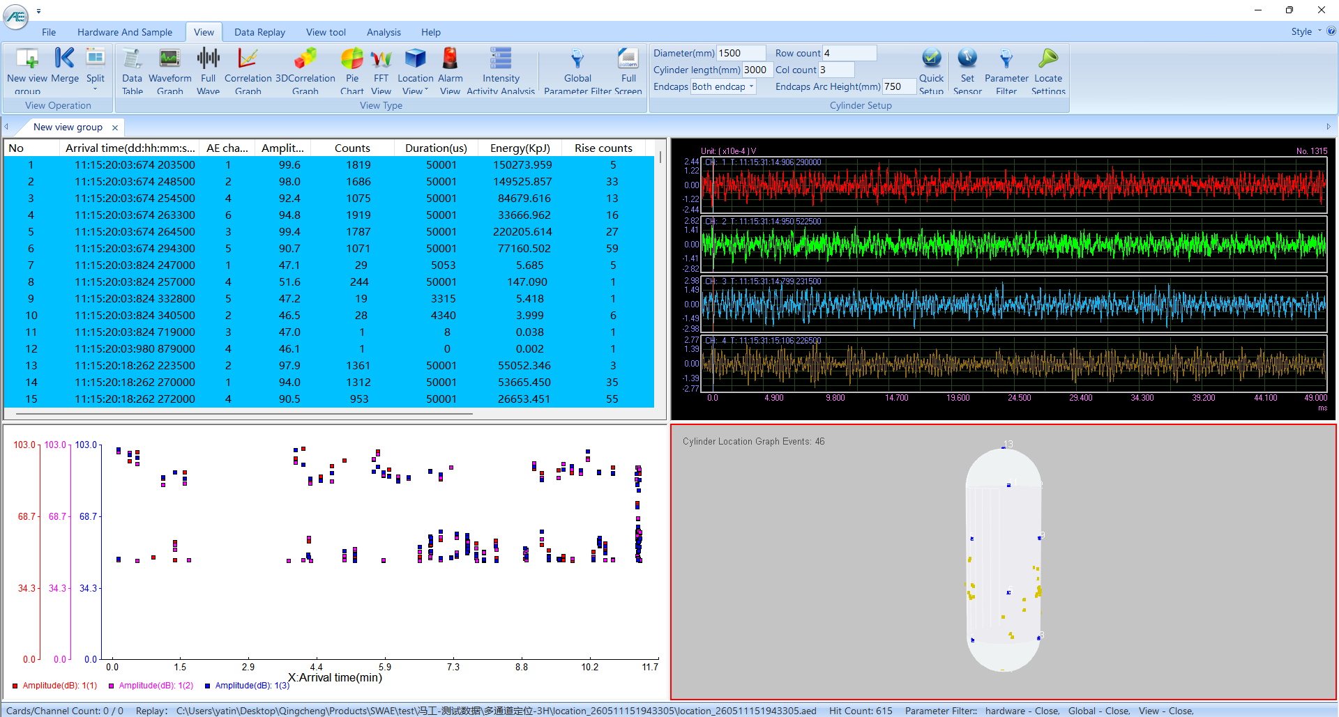
The pressure curve is analyzed together with AE activity. When AE signals suddenly increase during the same pressure increment or pressure holding period, the operator should pay attention to possible leakage, stress release, overpressure or structural failure risk.
Source Location
With multiple sensors installed on the vessel, the system can estimate the acoustic emission source location based on arrival time differences.
The location result helps identify suspicious areas such as:
- Weld seams
- Nozzle areas
- Shell sections
- Head areas
- Repaired zones
- High-stress concentration areas
- Areas with repeated AE events
For complex structures, location calibration using simulated sources can improve confidence in the location result.
Activity and Severity Evaluation
AE sources can be evaluated based on source activity and signal intensity. A source area with continuously increasing events during pressure increase or pressure holding may indicate stronger activity. A source area with high amplitude, high energy or repeated events may require further inspection.
AE evaluation usually considers:
- Whether events are concentrated in one area
- Whether activity increases with pressure
- Whether activity continues during pressure holding
- Whether signals repeat from the same location
- Signal amplitude and energy level
- Background noise and interference
- Vessel structure and operating condition
Follow-Up Inspection
AE testing identifies active source areas, but it does not directly provide detailed defect size, depth or morphology. When suspicious AE sources are found, follow-up inspection is recommended.
Common follow-up methods include:
- Ultrasonic testing
- Phased array ultrasonic testinge
- Magnetic particle testing
- Penetrant testing
- Visual inspection
- Thickness measurement
- Local structural evaluation
Typical Deliverables
A pressure vessel AE testing project can provide:
- Test plan and sensor layout
- Equipment and channel configuration
- Channel sensitivity verification results
- Background noise record
- Pressure loading curve
- AE activity trend
- Source location map
- AE parameter analysis
- Waveform or frequency analysis, if required
- Suspicious source area classification
- Recommended follow-up inspection areas
- Final test report
User Cases
Case 1
Acoustic emission detection of long tube trailer gas cylinders
Long tube trailer gas cylinder is a high-pressure storage and transportation equipment containing dangerous media. Whether timely and effective inspection can be carried out is the key to ensure its safe and reliable operation. Acoustic emission detection is an effective method to detect dynamic defects as a whole, which can save a lot of time, manpower and material resources when applied to the detection of long tube trailer gas cylinders.
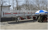
Fig. 1 Field detection picture
Case 2
Acoustic emission detection of gas cylinders
The main purpose of acoustic emission detection and evaluation of in-service high-pressure gas cylinders is to determine the effective location and severity level of the AE source. For the gas cylinders without serious AE sources, they can be safely put into service. For cylinders determined to have serious AE sources, it is necessary to use conventional non-destructive testing methods for retesting.
At the invitation of PetroChina Karamay Petrochemical Company, Qingcheng Company used SAEU2S-18 acoustic emission instrument to test a high-pressure hydrogen cylinder with a capacity of 4 cubic meters. The results showed that 3 meaningful AE sources were grade B, and no other non-destructive testing was required for retesting. The test results prevented customers from blindly replacing gas cylinders because they were not clear about the condition of gas cylinders, and helped customers save the cost and time of replacing new gas cylinders.
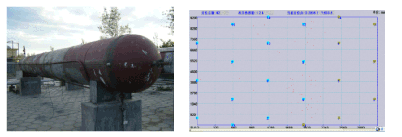
Fig. 2 Field monitoring picture Fig. 3 Diagram of AE source location of gas cylinder
Documents/Materials
 Acoustic Emission Testing Procedures of Pressure Vessels.pdf
 SAEU3H AE system HW and SW illustration on Compressed Air Vessel video
Pressure Vessel AE Testing vs Storage Tank AE Monitoring
Pressure vessel AE testing and atmospheric storage tank AE monitoring are different applications.
Pressure vessel AE testing focuses on active cracks, leakage, weld activity, fatigue damage and structural damage under pressure or loading conditions. Sensors are usually arranged around welds, nozzles, shell sections, heads and high-stress areas.
Storage tank AE monitoring usually focuses on bottom plate corrosion, leakage and active corrosion sources. Sensors are commonly installed around the lower shell of the tank.
If your application is an atmospheric storage tank or AST bottom corrosion monitoring, please visit our storage tank corrosion monitoring solution page.
FAQ
Q1: What is pressure vessel acoustic emission testing?
Pressure vessel acoustic emission testing is a non-destructive testing method that detects elastic waves generated by active defects or leakage while the vessel is under pressure, load or operating stress. AE sensors installed on the surface receive the signals, and the acquisition system analyzes the data for source activity and location.
Q2: Can AE detect cracks in pressure vessels?
AE can detect active crack growth when the crack releases acoustic energy under stress. It is most effective during pressure loading or operation. A completely inactive crack may not generate detectable AE signals, so AE is often used together with follow-up NDT methods.
Q3: Can AE testing locate the defect?
Yes. With multiple sensors and proper calibration, AE source location can estimate the area where acoustic emission signals originate. The result is usually used to guide follow-up inspection rather than directly replace defect sizing methods.
Q4: How many sensors are needed?
The number of sensors depends on vessel size, geometry, material, attenuation, expected defect areas and required location accuracy. Small vessels may need only a few channels, while large pressure vessels may require many sensors for full coverage and source location.
Q5: Is AE testing suitable for high-temperature pressure vessels?
Yes, but the installation method must be selected carefully. High-temperature sensors, thermal protection or waveguide rods may be required when the vessel surface temperature exceeds the limit of standard AE sensors.
Q6: Can AE detect leakage?
Yes. Gas, steam or liquid leakage can generate acoustic signals due to turbulence, friction and jet impact. AE sensors can detect leakage-related signals transmitted through the vessel wall or connected structures.
Q7: Does AE replace ultrasonic testing?
Usually no. AE is a global monitoring and screening method for active sources. Ultrasonic testing, phased array UT or other NDT methods may be used later to confirm and size the defect.
Want a Pressure Vessel AE Testing Solution?
QAWRUMS provides complete acoustic emission testing systems for pressure vessels, boilers, reactors, towers, coke drums and other pressure-retaining equipment.
Please contact us with the following information:
- Equipment type
- Vessel size and geometry
- Material and wall thickness
- Operating pressure and temperature
- Testing purpose
- Expected defect type
- Whether pressure loading is available
- Required monitoring duration
- Site environment and installation conditions
Our team will recommend the suitable AE system, sensor type, channel number, sensor layout, installation method and data analysis strategy for your application.
Contact Form
Please complete the form below to request your quote. We will be in contact as soon as possible.