Acoustic Wave (Acoustic Emission)
BRIDGE CABLE WIRE BREAKS MONITORING SYSTEM
Why use Acoustic Emission for Structural Health Monitoring
During the service life of the bridge, the bridge cable wire breaks are easily happened due to the influence of heavy load, environmental corrosion, stress corrosion, corrosion fatigue, hydrogen embrittlement, etc.
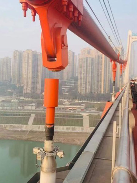
Therefore, structural health monitoring of bridges is very useful and necessary. Among the many SHM techniques, bridge nondestructive testing (NDT) methods are often applied, for example vibration, ultrasonic testing and infrared thermography.
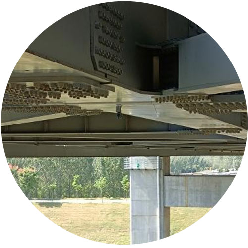
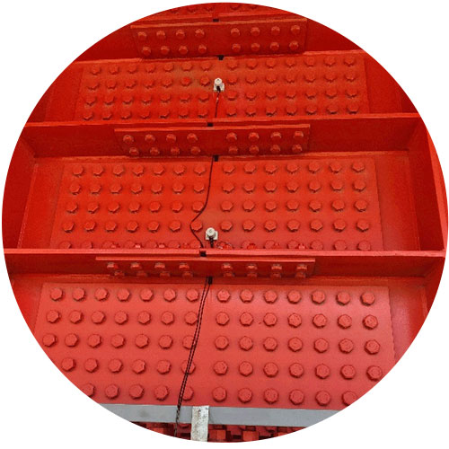
But acoustic emission technology is used widely and recommended for bridge health monitoring and bridge NDT equipment because of its real-time dynamic monitoring and high sensitivity of early initial damages. Some important parts of the bridges, such as bridge cable wire ropes breaks, anchors, girders and bolts tightness and more can use acoustic emission monitoring system for bridge structure monitoring.
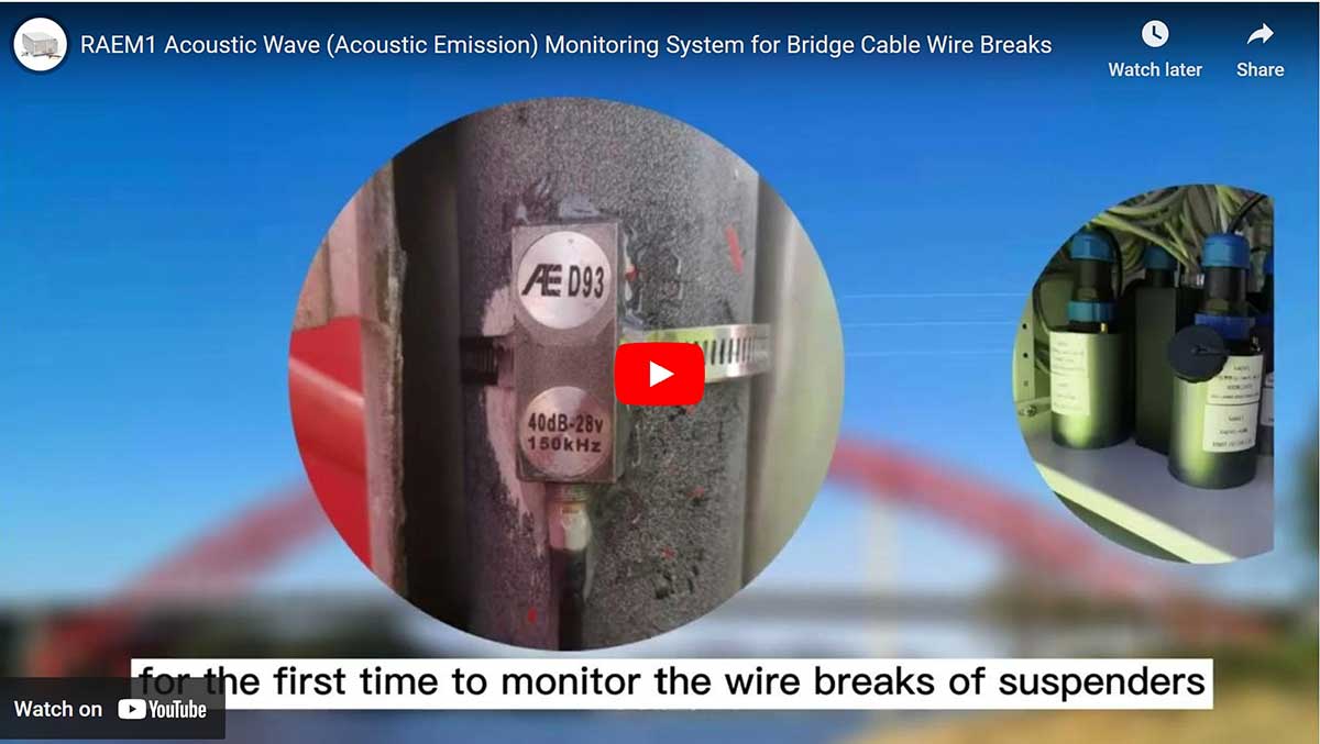
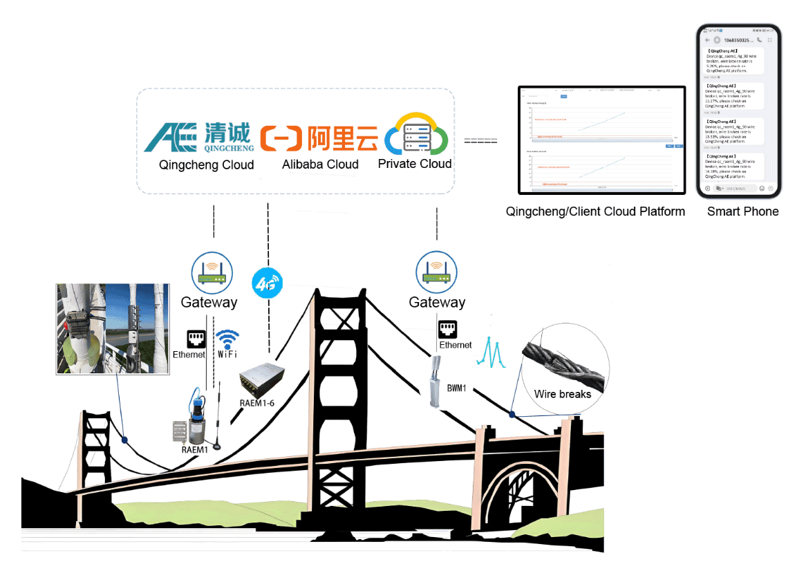
When the bridge wire breaks, a strong elastic wave will be generated and propagated along the inside of the steel cable to the acoustic emission sensor installed on the steel cable. The acquisition unit performs system processing analysis and calculates the characteristic parameters of the acoustic emission source, identifies and extracts effective wire breakage signals, and analyzes the wire breaks condition of the cable.

Process visualization
24/7 continuous online acoustic emission monitoring and detection, automatic analysis of the results of the whole process, and remote operation and use of the Internet of Things.
- Automatically give the detection and monitoring diagnosis results;
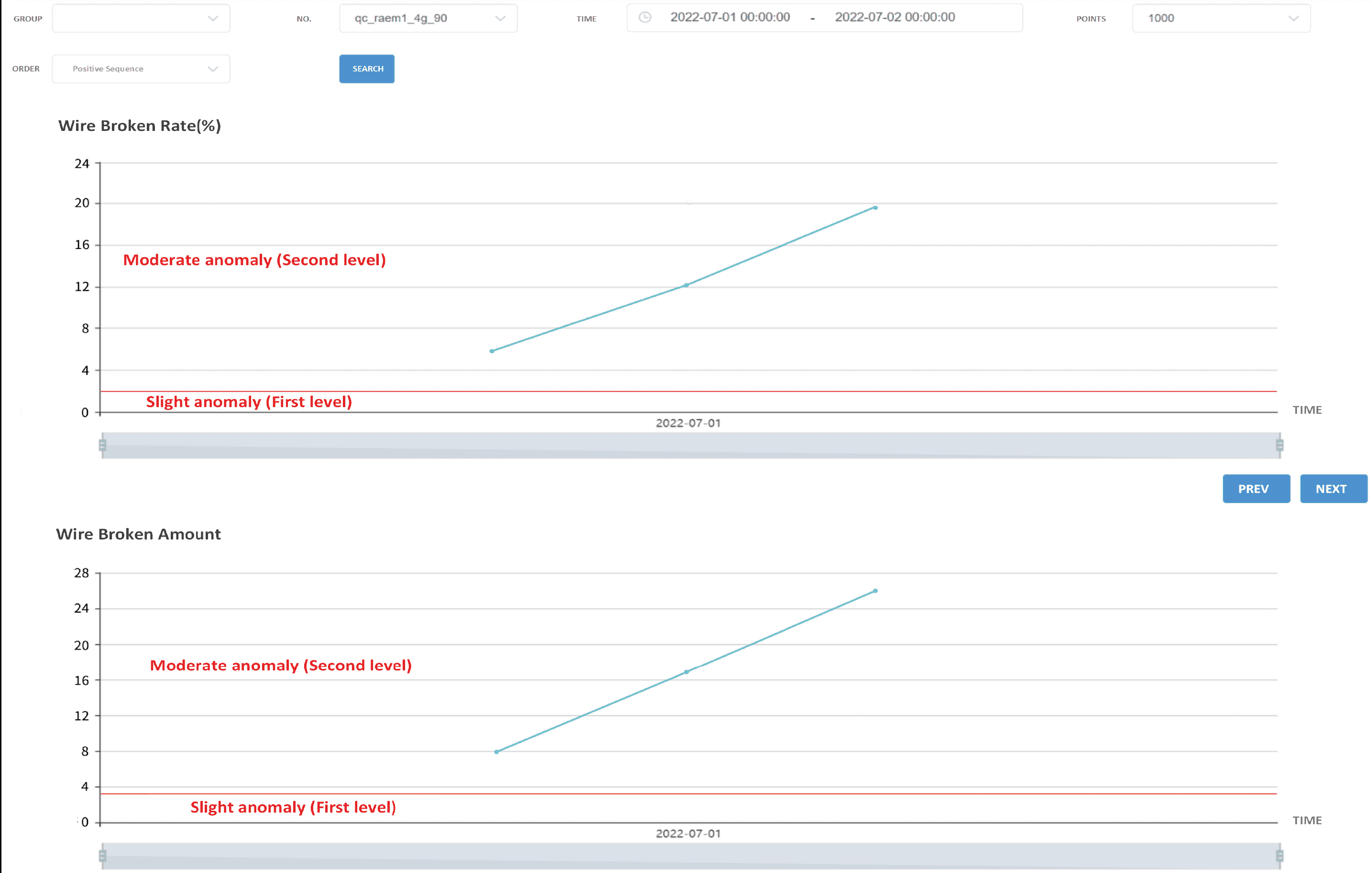
- Online and historical data screen display;
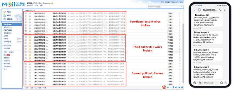
- Wire breaking alarm messages automatically pushed.
Results
a. Implement the monitoring and detection of wire breakage of suspension bridge slings and main cables, cable-stayed bridges, tied-arch bridge suspenders (cables) or tie rods according to the standard JT/T 1037-2022 Highway Bridge Structure Monitoring Technical Specifications;
b. Give the number of broken wires and the wire breakage rate of each cable according to the standard (the percentage of the number of broken wires to the total number of cables is the wire breakage rate);
c. Users can carry out inspections, repairs and cable replacements in a timely manner according to the standard content to prevent losses and accidents caused by the accumulation of damages.
Scopes of Applications
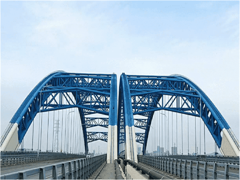
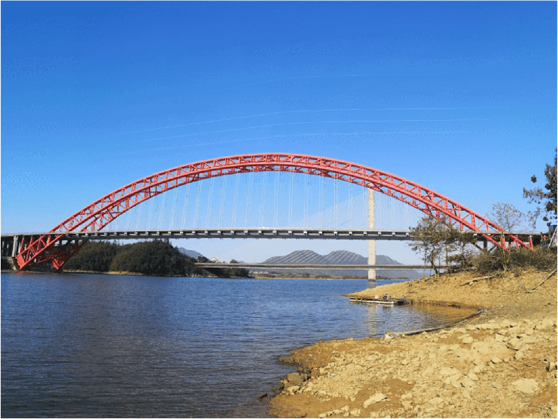
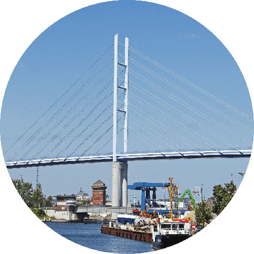
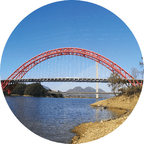
Wire breaks monitoring of suspension bridge slings and main cables, cable-stayed bridges cables, tied-arch bridge suspenders (cables) or tie rods.

Suspension Bridge
Main cables & suspenders
Cable-stayed Bridge
cables
Tied Arch Bridge
Hangers
Bridge Girder
Bridge Bolts
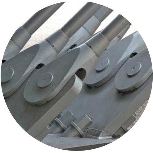
Bridge Anchors
Solutions
Solution 1: Chain Type Bridge-Specific Acoustic Wave (Acoustic Emission) Monitoring System - BWM1
Principle: When a bridge cable breaks, a strong elastic wave will be generated and propagated along the inside of the steel cable to the BWM1 acoustic wave (acoustic emission) monitoring system installed on the steel cable. The system identifies and extracts effective wire breaking signals and analyzes the wire broken status of the cable.
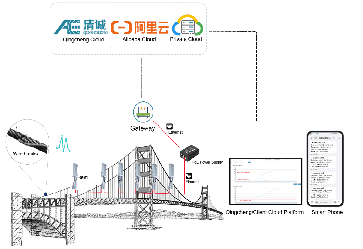
| System Components | Communication Method |
| BWM1, POE, Router | Ethernet |
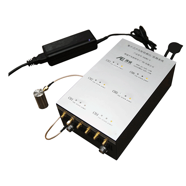
Solution 2: Centralized Acoustic Wave (Acoustic Emission) Monitoring System - RAEM1-6
Principle: When a bridge cable wire breaks, a strong elastic wave will be generated and propagated along the inside of the steel cable to the acoustic emission sensor installed on the steel cable. The RAEM1-6 multichannel acoustic wave (acoustic emission) monitoring system identifies and extracts effective wire breaking signals and analyzes the wire broken status of the cable.
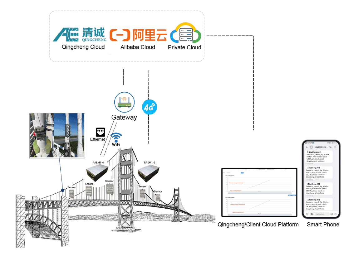
| System Components | Communication Method |
| AE sensor, RAEM1-6, Cloud server, client terminal | 4G, WiFi, or Ethernet |
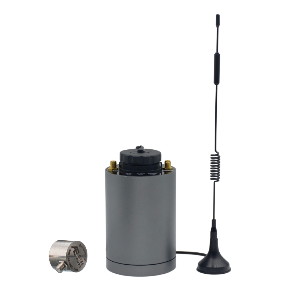
Solution 3: Distributed Acoustic Wave (Acoustic Emission) Monitoring System - RAEM1
Principle: When a bridge cable wire breaking happens, a strong elastic wave will be generated and propagated along the inside of the steel cable to the acoustic emission sensor installed on the steel cable. The RAEM1 acoustic wave (acoustic emission) detection system identifies and extracts effective wire breaking signals and analyzes the wire broken status of the cable.
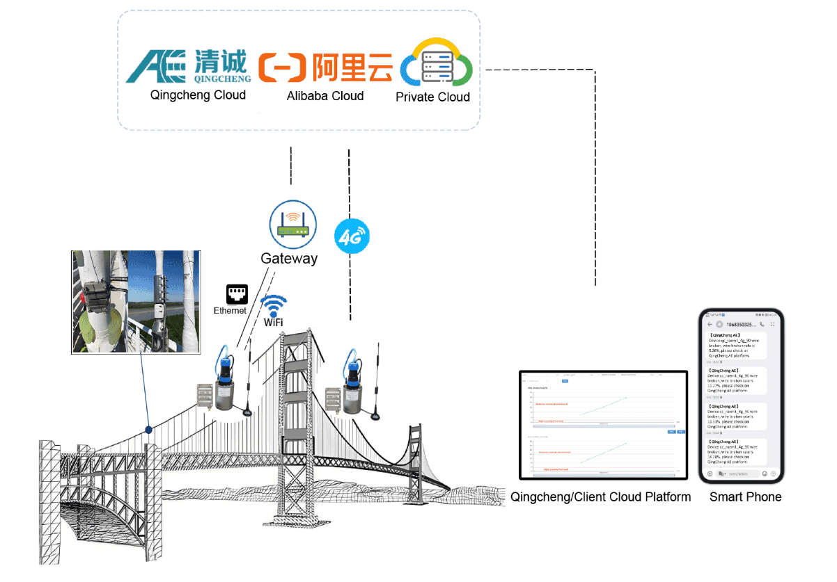
| System Components | Communication Method |
| AE sensor, RAEM1, Cloud server, client terminal | 4G, WiFi, Ethernet, RS485 |
Equipment Introduction
Based on the previous three monitoring solutions, the hardware parameters and advantages of the three devices are introduced.
| Picture |
 |
 |
 |
| Model | BWM1 | RAEM1-6 | RAEM1 |
| Sample Frequency | 2M points/sec maximum per channel | 2M points/sec maximum per channel | 2M points/sec maximum per channel |
| Sample Resolution | 16-bit | 16-bit | 16-bit |
| Channel | Single channel | 2 to 6 channels or cascade | Single channel |
| Frequency Range | 10kHz-800kHz | 10kHz-800kHz | 10kHz-800kHz |
| System Noise | Better than 30dB | Better than 30dB | Better than 30dB |
| Dynamic Range | 70dB | 70dB | 70dB |
| Communication | Ethernet | 4G, Ethernet, WiFi | 4G, Ethernet, WiFi, RS485 |
| Sensor Built-in | Center frequency at 40/150KHz optional; two built-in preamplifier gain optional: 20/40dB | / | / |
| Power Supply | PoE power supply | 12VDC | 12VDC |
| Dimension | 507*50*43mm (water-proof cap included) | 220 x 130 x 80 mm | Cylinder diameter 62mm, height 100mm |
| Weight | 285g | 1.6kg | 220g |
| Installation | Bandage (clamp) structure | / | magnetic bottom and can be adsorbed on the surface |
| Protection Degree | IP67 | / | IP65 |
| Operation Temperature | -30℃~+70℃ | -20℃~60℃. (WiFi version is 0℃~60℃) | -20℃~60℃. (WiFi version is 0℃~60℃) |
| Single Node Connection Distance | Max 400 meters Ethernet cable and connect 6 devices in series | / | / |
| Advantages | Chain series connection refers to connecting the BWM1 with built-in sensors in series with Ethernet cable through a PoE power adapter, realizing data transmission through the PoE and simplifying the wiring method of the sensor. | Based on the Linus system, it has stable performance and wireless communication capabilities, making it suitable for long-term remote unattended monitoring. The equipment can be cascaded to form a large monitoring system. | The acoustic emission detector has built-in signal processing and communication modules, and its bottom is magnetic, so the device can be directly coupled to metal objects during installation. |
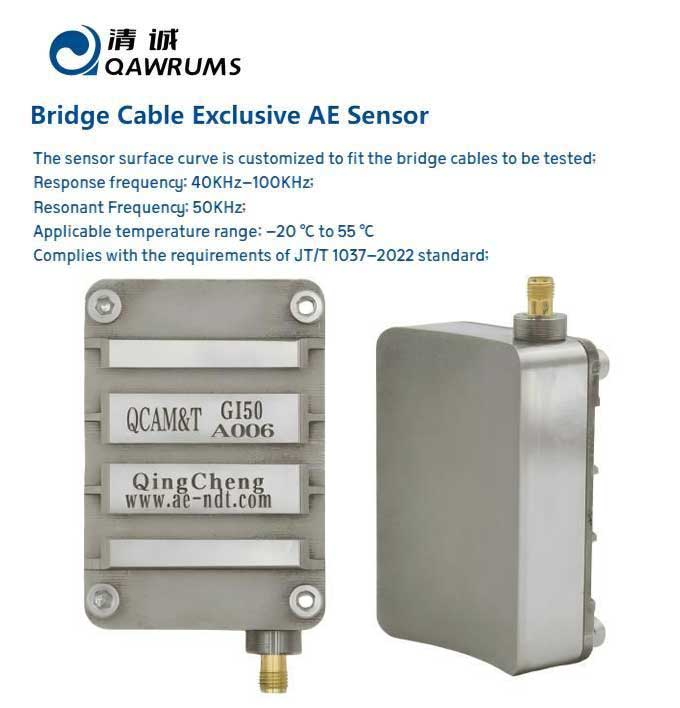
Bridge Monitoring Sensors (Exclusive for Bridge Cable Monitoring)
- The sensor surface curve is customized to fit the bridge cables to be tested;
- The Attached Type acoustic emission sensor response frequency: 40KHz-100KHz;
- Resonant Frequency: 50KHz;
- The sensors have built-in preamplifier;
- Applicable temperature range for attached acoustic emission sensors: -20 ℃ to 55 ℃ (with a service life of 5-10 years) Complies with the requirements of JT/T 1037-2022 standard.
Process
1. Install equipment in key parts of the bridge and detect and monitor steel wire ropes;
2. Reasonably configure collection parameters and rating parameters;
3. Start monitoring, once a wire breakage occurs, the mobile phone and cloud platform will push an alarm message.
Installation
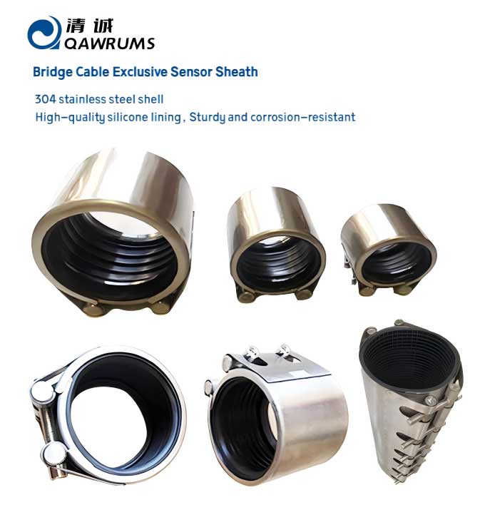
Install on the suspension cables, main cables, cable-stayed cables, arch bridge suspenders (cables) or tie rods that need to be detected and monitored. The wire breaks measurement points can be arranged at the end of the anchor head or attached to the outer surface of the cable sheath.
Qingcheng Cloud Platform
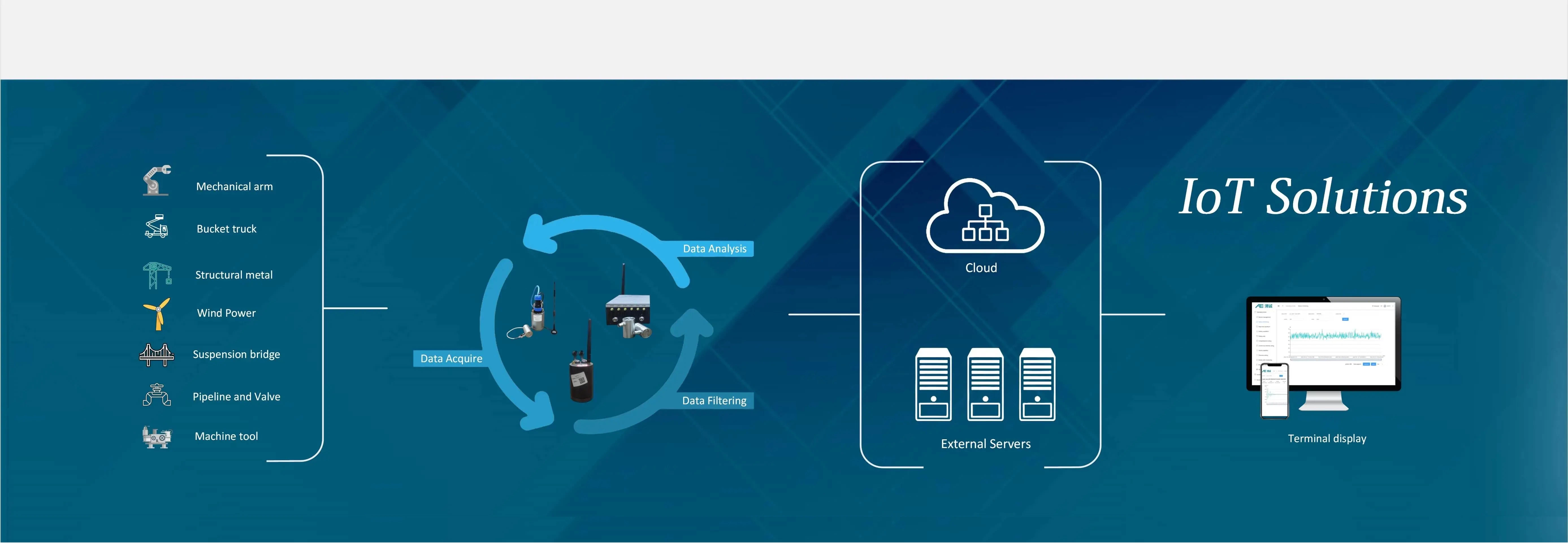
The data is uploaded to the cloud IoT platform (Qingcheng Cloud) for display and analysis. AE characteristic parameters: arrival time, amplitude, ASL, Energy, RMS, Duration, Counts, Rise Time, Rise Counts, Peak Frequency, Frequency Centroid, & 5 Partial Power Spectra Segments.
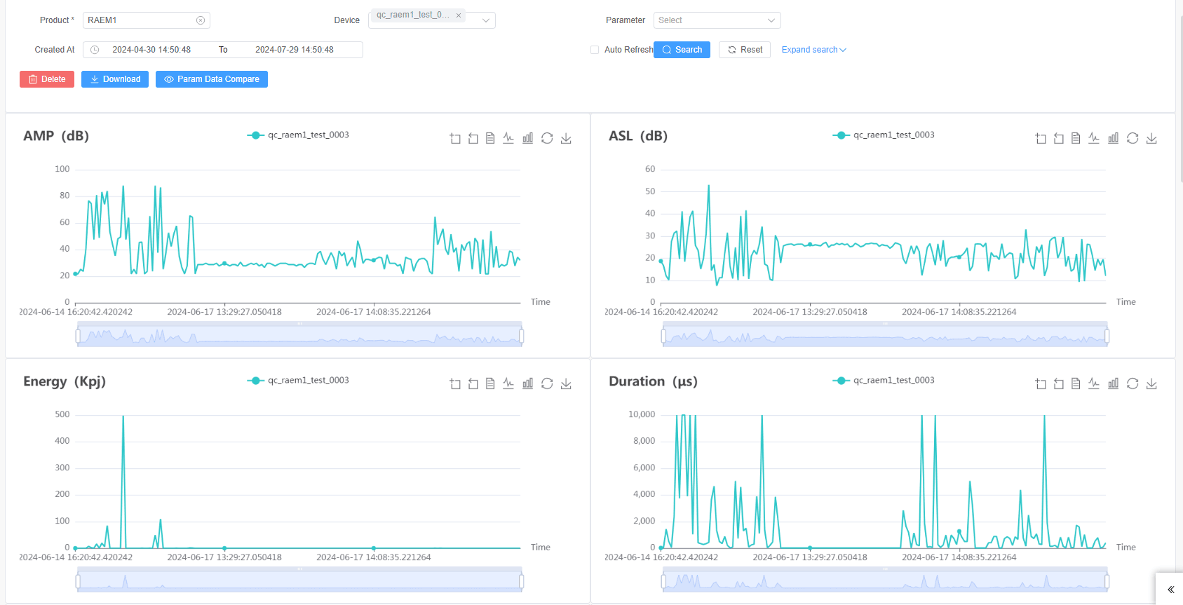
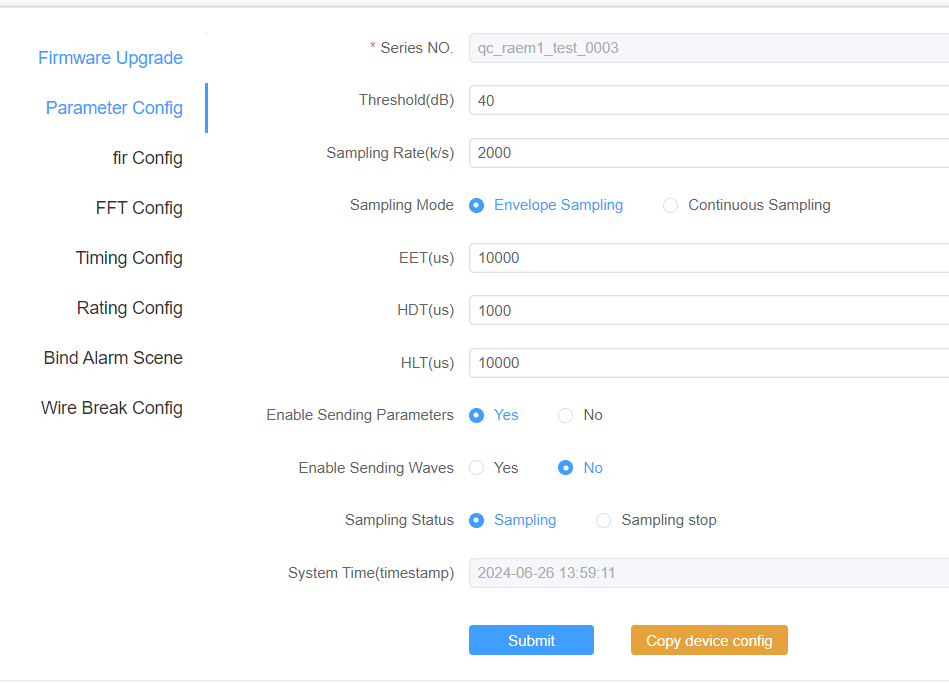
Remote configuration: remote configuration parameters, timing configuration, wire break rating settings.
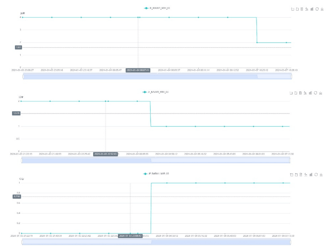
The system automatically rates, and the rating results can be viewed remotely on the cloud. The acoustic emission data uses an automatic grading algorithm to obtain the intensity level, activity level, and comprehensive level from the acoustic emission characteristic parameters. Flexible settings can meet the rating requirements of different industry standards.
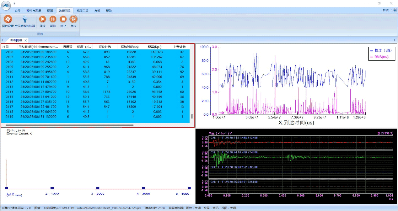
SWAE software
The SWAE acoustic emission system software is a combination of real-time acquisition and analysis and post-analysis software. In addition, SWAE software can be used for in-depth analysis and processing to understand the details of defects in detail, such as parameter analysis, location analysis, correlation diagram analysis, waveform analysis, fast Fourier transform, wavelet transform rating analysis, etc.
Case Study
Full size bridge cable rope wire breakage experiment:
A successful acoustic wave (acoustic emission) monitoring experiment on a full-size bridge cable steel rope was conducted by a joint team from QingCheng and a bridge cable manufacturer.

Diagram of full size bridge cable rope wire breakage experiment
(P1 is the wire break position, S is RAEM1 monitor position)

*Note: it conforms to the standard JT/T1037-2022 “Technical Specifications for Highway Bridge Structure Monitoring” and refers to “Over Limit Level” in Table 9.
- Level 2: when the wire break happens;
- Level 3:the rate of wire breaks > 2%
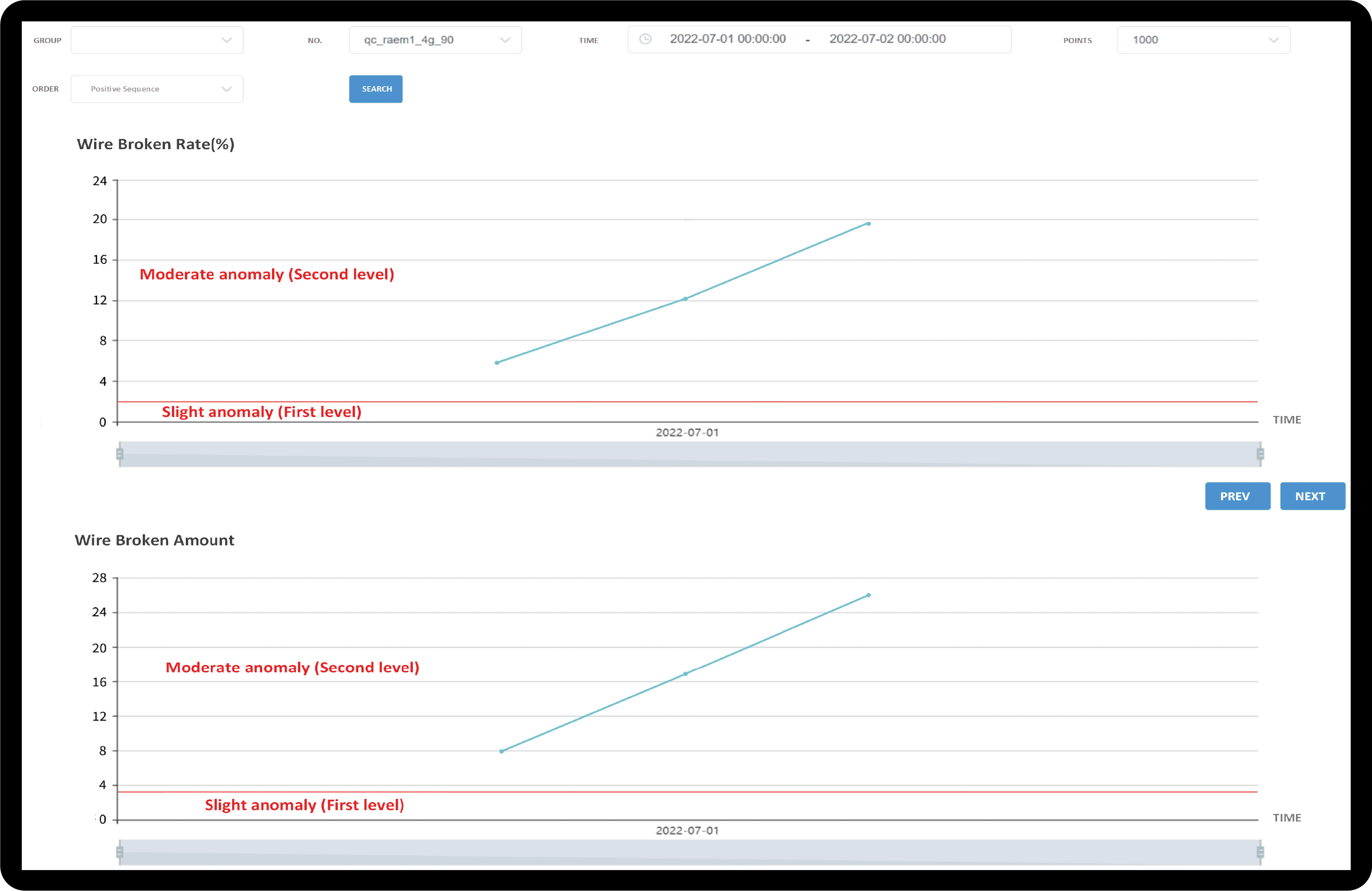
Real-time display of the number and rate of wire breaks
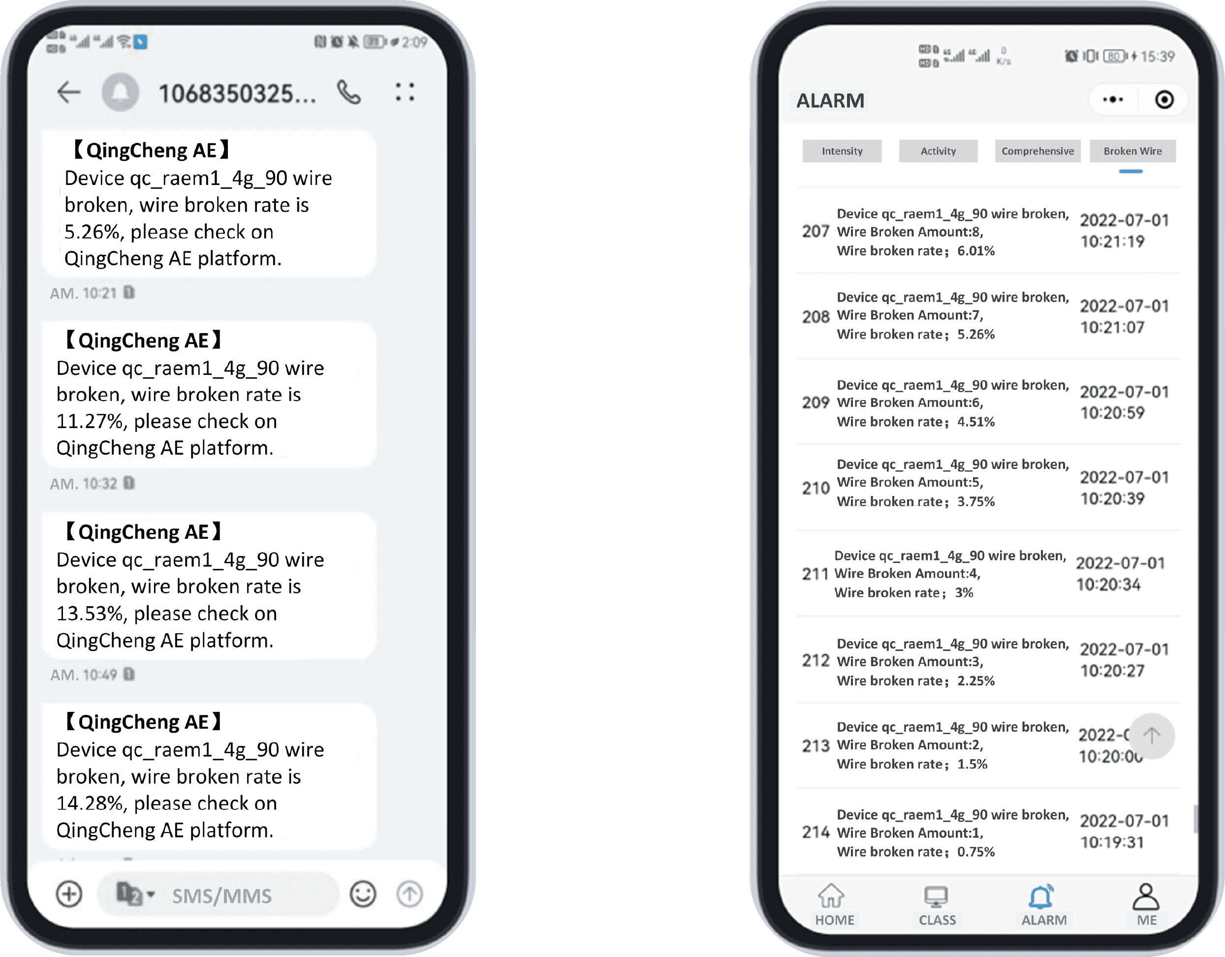
Alarm notification through e-mail or SMS
Users Cases
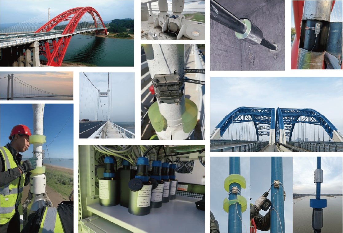
- Taiping Lake Bridge
- Heliuye Bridge
- Mingchuan Road Bridge
- Maanshan Bridge
- Qingxi West Road Bridge
- Ningjing Si Bridge
Cases Study
Contact Form
Please complete the form below to request your quote. We will be in contact as soon as possible.

